Tuesday, January 31, 2017

DeWalt GE Radial Arm Saw rebuild Part 5, elevating mechanism, column and arm

I began the dis-assembly of the under mounted elevating mechanism; as it certainly was going to need a thorough cleaning. I removed the handle, (on the Long Arm version it's mounted in front) and loosened the bracket, which is held on by two bolts. The handle has a spring loaded mechanism to lock the handle when it is turned out to the 90 degree out position. Pull that pin out, turn the handle back in so it doesn't protrude when not in use. My spring pin is quite stiff, I'll deal with that later.

There is a pin and set screw holding the handle assembly to the shaft. The table has a lot of bad spots, its going to be a lot of work to get that in good shape. I ordered a new badge for the front, the current one is beyond cleaning and repair.


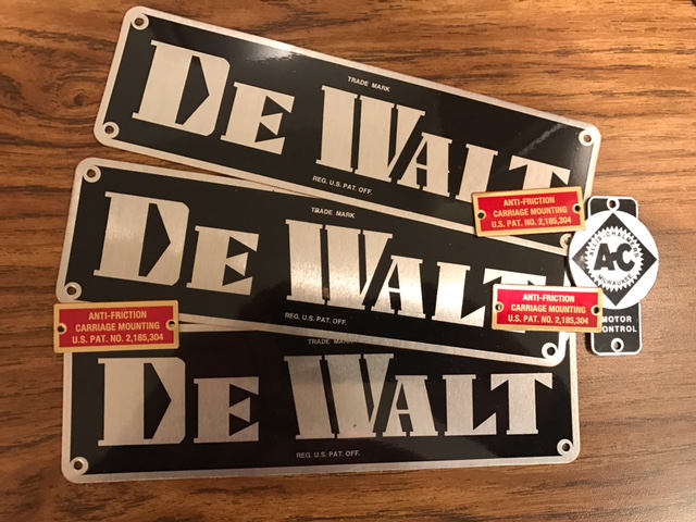
Here are the replacement badges I had to have made so far for this machine.
The red badge is from the motor housing and the AC badge is for the magnetic starter box.


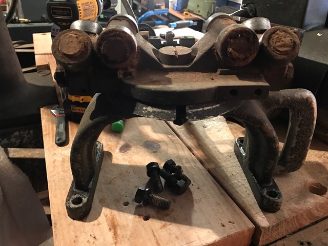
The other end of the shaft the handle assembly is mounted to, has a bolt securing it. The bolt also has a spring clip that must be removed before the nut can come off. The gear unit comes right off after removing the three cap head screws that hold it to the housing under the column. The unit and shaft should come off together. What a royal mess that was inside! Clearly no one that owned any of the saws I've acquired ever read Jon Eakes's book on radial arm saws, because no one ever kept any of those machines clean. That housing is full of grease laden sawdust.


There are three cap head screws that hold the column housing to the underside of the column base.
They are very tough to get to as they are recessed and its a tight fit from the frame to the side of the column housing. You will need a socket with a 5/16 Allen head and a 12 or 18" extension, you need a long reach from the underside of the table to reach the heads. I used that combination in my DeWalt impact driver on its slowest setting, they came right out. The housing slips right off.

Removing the column base using isn't all that difficult but accessing the bolts on the underside is a bit cumbersome , the same as the prior procedure. I had to use a 24" breaker bar with a 7/8" socket to hold those bolts while my nephew ratcheted off the bolts from the top of the column base. The other two are slotted flat head bolts, but their nuts are 1 1/16".

Once the hardware is all removed you can remove the base and column. Lay it on a table as you have to remove the bushing and the elevating shaft from the bottom of the column. The bushing is secured by four bolts which bolt directly into the bottom of the column ring. You can see the four mounting holes for those bolts in the picture below.


The housing, the lower gear cover and the bracket are all going to have top be thoroughly cleaned, sanded, media blasted and painted.

I had a tough time removing the bushing from the end of the column. Upon peering down the column from the top I could something lodged at the bottom next to the elevating screw which was preventing it from turning more than 1-2 turns. It turned out to be the elevating screw top, which is essentially a 3/16 inch thick stainless steel washer which is bolted into the threaded center of the top of the elevating screw, its job is to keep the elevating screw centered in the column. Its bolt somehow had sheared threads and it had come off and lodged in the bottom of the base. It took some finagling, and a bent wire hanger but I got it out. Then the bushing, once unscrewed, came right off. The piece lodged on the bottom did mangle some of the threads on the elevating screw as I could only remove it from the bushing by unscrewing it up out the top. You can see the mangled threads in the lower portion of the screw here, they are also mangled at the top. Hopefully I can find a replacement or I will have to send it out to a machine shop to be custom made, that won't be cheap.

EDIT: Bradley Tools & Fasteners of Johnston, IA bought out the DeWalt radial arm saw parts inventory. I was able to get the elevating screw, the cap, the thrust bearing for that screw and the dog screw for the king bolt through them.


I cleaned all the hardware and gear from the end of the elevating screw as they were crudded up with greasy sawdust. 


The bushing was all full of that greasy sawdust too but that cleaned up rather easily. Would it be too much if I polished it with brass polish? Here it is just cleaned with Scotch-Brite. As you may know, brass looks like cast iron until it is machined, you can see the difference as the important parts are machined, the rest are raw.


There is also a bearing on the elevating shaft, this one HAS to be original; I've never heard of the Nice Ball Bearing Company, have you?


It will probably be tough to find that new. If I can't I'll have to clean and re-grease it. I hate doing that.
EDIT: See my edit above about where to source this bearing.

I cannot get the column to come out of the base. It is cold in the garage, so I'm assuming that has something to do with it. I used Kroil in the keyway and the edge where the column meets the base, we will see if that frees it up other wise I'll have to try heating the base.

It is time to finish paint removal and media blasting for the parts that require it from the base and arm assembly. Doing a full restoration requires a lot of painting and prep work. Fortunately, last year I found a brand new,unused, Grizzly 48" sand blast cabinet on craigslist for 25% of its retail cost. It has paid for itself many times over.


Part 6 will round-out the base and column (assuming I can get the darn column out of the base!) and go over the arm and carriage assembly. I'm also hoping to complete Part 4A, wiring the motor up to the starter for testing soon as well.

Wednesday, January 25, 2017

DeWalt GE Radial Arm Saw rebuild Part 4, rewiring the motor and starter

As promised part 4 is all about the re-cabling of the saw. In part 1 I showed how I rewired the switch in the end cap with new 12/3 SJOOW portable machine cable. The other end of that cable gets connected to the magnetic starter control box as does the power cable to the motor and the 230V wall outlet.

Although very stout when built, the wiring in these saws is over 60 years old. The original wiring is cloth covered and that cloth erodes over time. As you can see below, this is why the saw needs new cable. That wire is an accident waiting to happen with the break in the sheathing near the terminal, that exposed wire is a problem which has to be corrected.


The magnetic starter control box will likely be different on your saw. I have two GE's and have seen 2-3 others and NONE of them have the same make of control box. This is likely due to the fact that they may have been replaced prior. They all do operate the same however, they assist the motor in starting up.

Here is what my box, which is badged Allis-Chalmers, with Square D electricals inside, looks like.


The first thing to do is thoroughly clean everything inside the box. I blew all dust and sawdust that remained from my first general cleaning out with my compressor. I then vacuumed anything else I could get out. Using a Q-Tip with a little dish soap on it, I cleaned around all the terminals and all the areas you see that are black phenolic. I used a dry Q-Tip to clean any additional muck and crud that was in there.

I then prepped it for repainting as I wanted it gloss white to match what the table will look like. I stuffed it very well as I didn't want any of the electric parts to get paint on them.


Now that the box is as clean as I can get it and repainted; it is time to start the re-wiring process. There is no correct order. I started with the smaller 12/3 cable that comes to the unit from the on/off switch in the end cap. Yes, I'm aware that I will have to disconnect this to put the switch back in, I am doing it for educational purposes here so this material relating to the electrics, is all in one place.


In the photo above, you can see the three leads coming out of the conduit hole at the bottom right of the photo. Wiring colors were somewhat different back in the 40's and 50's. I see some three wire schemes black/red/green and others black/white/green and sometimes the red or white is brown. Just match your wires to their original mates if the saw was operational when you started working on it. If not there will be another post on troubleshooting the electrical components if your saw is not operational.

In my case, the wires for the starter were black/red/green. Since my new cable was black/white/green, they each connect to its like colors terminal, with my white replacing the old red.


You can see in the photo above I used 10-12 size ring terminals and heat shrink tubing to secure the connection. DO NOT FORGET TO CRIMP YOUR RING TERMINAL. Below, you can see the newly connected wires for the start switch.


I moved on to adding the cable for the 230V power outlet. I put a 50 amp plug on one end of this cable, Sorry but I forgot to take any pictures of that process. It's pretty simple as the instructions come with the new plug. If your undertaking a project like this, then I'm sure I don't need to go into how to rewire a new plug.

As you can see in the photo below (bottom left corner), I used a 3/4 inch lock tight waterproof connector. I did so for aesthetics and because the lock tight connector will keep a lot of dirt and sawdust out of the enclosure. It is important to start with your leads long enough so that you can cut them slightly to the proper length so they fit properly inside the box.

For each wire I do the following


  • measure and cut it so it exactly fits the length needed to reach its terminal with a little wiggle room
  • strip 1/4" of the wire end
  • slip the heat shrink over the wire
  • put a 10-12 ring terminal on the end making sure some of the copper strands protrude from the ring terminal opening
  • crimp the terminal
  • slide the heat shrink over the terminal to the bottom side of the ring
  • heat it so the heat shrink shrinks around the ring terminal
To heat the heat shrink tubing you can use a heat gun, blow dryer, lighter or a match. They all work, the first two are a little cleaner.


Here is the new plug cable and connected. You can tell the new wires as they have heat shrink around the terminal connections.


I then moved on to wiring the cable for the motor. I have 30 ft of 10/3 SJOOW portable machine cable for this. I won't be 30 ft, the old cable which I believe was original, was 15 ft long. I will cut it when necessary to the proper length.

The conduit hole for the motor wiring wasn't big enough for the 3/4" lock tight connector. I had to drill out the hole carefully so as to not damage any of the wiring inside the control box to 1" so the connector would fit. The process was the same as for the plug wire so Ill spare you the details. Here is the new wring inside the control box.


The whole process took about an hour, including the time it took me to put the plug on the other end of that cable. That plus the $85-90 for all the new cable.

Here is the completed (almost) unit.


I say almost completed because there was an odd shaped Allis-Chalmers badge, which mounted on the two holes you see in the cover. It was all scratched up and faded, but legible. I hated to put that back on so I went to the expert in badge replication, Jim Kull. You can find him on PracticalMachinist.com. It was pricey as it was an odd shaped piece but I figured if I'm going all the way, then go all the way! You can see the new Allis-Chalmers badge below along with the other two badges I had remade due to their poor condition. sometimes it is cheaper to have a replacement badge made than to spend hours trying to clean up a badge that is beyond repair. I always buy a few extra, it makes them cheaper per badge and if I don't need the extras I can always sell them for what I paid for them. I needed two each of the DeWalt's anyway as I'm restoring two Model GE's.


I am finishing up painting the motor, when it is finished Part 4A will be wiring the motor to the starter and testing if it still works!


Tuesday, January 24, 2017

DeWalt GE Radial Arm Saw rebuild Part 3, assorted part overhauls

Now that I have the motor off, the carriage and yoke separated, and the motor holders off the side of the motor I can begin to clean all those parts and get them ready for paint. I can do the blade guard and it's holding ring as well.

All those parts will be blue, although I think I will keep the blade guard white, I'm not sure at the moment.

I also removed the magnetic starter box from the base. It's a bit rusty and the badge on it is damaged so I will clean that up and repaint it as well. I will have Jim Kull make a new badge to go back on the unit. The previous owner, an artisan woodworker, told me the saw ran fine although he didn't use it much so I am assuming the starter still works. It is original to this saw as it is an old Square D sold by Allis Chalmers and it's badged Allis Chalmers. It has all the instructions on paper glued to the inside of the cover written by hand (but then copied). It will be nice if it works as is, but I may have to upgrade to a newer NEMA magnetic starter to stay within code. We will see. I will be replacing all the wiring on this saw. The main wire for the plug and the wire to the motor are 10/3 SJOOW portable motor cable.

Here are some pictures of the starter.


As is, once I took the cover off. Very dirty and full of sawdust.


Sanded smooth and cleaned with acetone. ready for primer. I stuffed it really well with shop towels so no parts of it would get paint on them.

The photos below are the starter control instructions that are glued to the inside of the cover.


I will have an entire post on the re-cabling of this saw and the wiring for the end cap switch and the magnetic starter. It will likely be post #4 assuming the 10/3 wire I ordered gets here in the next day or so.

The miter lock handle, the one on the left in the photo below, comes out by tapping the shaft out from the left side when facing the saw from the back. Use a steel punch that is slightly smaller diameter than the shaft.

I was having trouble removing the handle that locks the arm. It is the handle at the top of the column, next to the miter lock handle (the one on the right in the photo). It has a flat head bolt shaft. Once I removed the handle, I wanted to take the bolt out but its really in there tight. The flat head was already damaged so I may just clean the threads and leave it alone. Ruining that bolt trying to loosen it will be an added expense of both time and money.


I sent a message to some people who had done prior GE restorations for advice. The trick here is the arm just rotates off the shaft, but you have to move the arm to the side so the handle can spin all the way around to come off (It spins clockwise)

As I noted before, my handles will all be red on this rebuild. The handles were sanded, media blasted, primed and then painted with two coats of white gloss. Once those dried thoroughly, I taped off the shafts and painted the handles with two coats of red and one coat of clear coat. I think they look good but maybe it's only me.

EDIT: In touching up some of the white parts of the handles, I taped off the red using blue painters tape. When they were dry and I removed the painters tape some of the red paint came off. Why you ask? Because the red was applied over the white (paint should be applied to primer) as I had painted the handles all white first, that was a mistake. If you are going to do handles, or anything else like this, prime the whole handle, two coats, then mask off the color separation after the primer has dried for two days. Paint your first color, three coats. Let the last coat cure for two days and remove your masking, the primer should stay intact. Using SCOTCH tape, as it is less sticky mark your color separation line and then use a Zip-Lock bag with the zip cut off and mask the painted part so that the blue tape sticky side is on the scotch tape you used to mark the color separation line. Then apply three coats of your secondary color. Let the last coat cure for a day and then remove the masking tape, bag and scotch tape. Your first color should remain intact. Let it cure one more day then apply two coats of clear coat enamel.


Blade guard positioning handle, the shaft is white as the guard will be. The funnel came in handy as a stand.


The yoke will be white and the motor is going to be blue, who can see my painting error here?


I replaced the motor bearings and cleaned up the motor, it purrs. Now I just have to get it ready for painting.

The bevel scale was filthy but it cleaned up very nicely and some brass polish made it really look good. Unfortunately it has some bad scarring at the 11 o'clock position, otherwise it is in good shape.
I will be replacing the mounting screws with brass screws (It had crappy SS ones originally)


The elevation mechanism is the next on the list. The handle is fairly easy to remove although I'm not thrilled with the fold up handle design but I see why they did it that way. As with the other handles, this handle will be red. I am going to test the red Plasti-Dip on this handle. If I like how it comes out, I will do all the others. If I don't, then I will re blast it and just paint it.

The screw and gear need serious cleaning as they are very dirty and rusty, as was a lot of this saw. They will be looking good when I finish and they will function better because of it.

I will also be lifting the arm off tomorrow and removing the base and column. All that in Part 5 (Part 4 will be all about re-wiring the saw).

Saturday, January 21, 2017

DeWalt GE Radial Arm Saw rebuild Part 2, yoke, carriage and bearings

Once I had the motor removed from the yoke, I began the process of removing the bearings from the carriage. A GE has eight bearings on the carriage. At the front and back there is a removable end piece that holds two bearings. There are many set screws, 12 in all If I remember correctly, that MUST be removed before you do anything else.


I cleaned all the bearings off with the compressor and the jet nozzle. I then sprayed them again with PB Blaster. The bearings come off quite easily in most cases. I start them off by squeezing a medium screwdriver behind them and twisting it up. This gets the bearing shaft moving out of its hole and usually you just pull them out by hand at this point. If not, I use a small three jaw puller (OTC part number 1021). This is a smaller puller and ideal for these size bearings. It is a $20 tool that is well worth the expense.


Important: On some models there are small, solid brass shims under the set screws that attach to the threaded bearing shafts. Don't lose them, they are hard to replace. They generally fall out when you pull the shaft and the bearing out of its hole.

You will not be able to get the top bearing by the lock knob off without removing the knob.
This is a tricky knob to remove. Facing the knob, loosen the left side bolt which has the left side shaft for the bevel. Then unscrew the right side as far as you can. You can now remove the clamp. You will notice that you CANNOT remove the right side bolt by unscrewing it as the shaft won't fit the threaded hole. The way you get that out is by screwing it all the way out thru the left side. A long flat head bit in your screw gun works very well to do this.

Once you have the bearing shafts off, it is time to separate the bearings from the shafts. There is a thin shim washer on each bearing shaft, be careful not to damage or lose them.


Once removed the washers and shafts can be soaked in WD-40 for a while; then cleaned and polished. There is a lot of talk about restoring old bearings, I'm not in favor of that. The difference in operation of new bearings versus restored bearings is DEFINTELY noticeable, restored bearings will last maybe a year before you have to do it again, the time & materials spent soaking, cleaning, re-greasing and installing the restored bearings isn't all that much cheaper than buying new ones. If you really want to talk about cost differential, all that has to be considered.

Once I got all the bearings removed from the bearing shafts I cleaned them thoroughly, including using a Q-Tip to clean the little recesses at the end of the shafts.


Now those are going to function a heck of a lot better than the way there were, all crudded up with rust and sawdust muck!

I then started to clean all the hardware I had removed so far from the yoke, motor and carriage.
I soaked all the parts in a mixture of WD-40 and white vinegar. Here are some of the parts waiting to be cleaned.


Here is where I was sitting while I cleaned all the parts. Nice place to do this work.


To clean the parts and hardware I used a combination of emory paper, small wire brush, a flap wheel, buff wheel and wire brush on a small cordless drill and scotch brite.

Here are some of the parts cleaned and ready to go. ALL PARTS ONCE REMOVED FROM THE MACHINE SHOULD BE BAGGED AND TAGGED!. And immediately after cleaning they go right back in the bag.


Light not so good on the picture above, trust me they are nice and clean.


I am painting this restoration in a USA theme, red, white and blue. The base, column base and arm will be white, the yoke and motor will be blue and all handles and the arm end cap will be red. I thought the end cap being red would contrast nicely with the white arm and the black on/off button switch that insets into the cap.

Here are some before and after handle pictures.


 This is the base of my GW-2 I just finished, the GE base will look the same, only a LOT bigger.


The shafts of these crank handles will remain white, the actual handle will be painted red although I am toying with the idea of dipping them in red plasti-dip so they have some grip on them. Love to hear comments on that.

The next post will cover the yoke and carriage cleaning, the cleanup of the magnetic starter box; including all new wiring and some motor work.


Friday, January 13, 2017

DeWalt GE Radial Arm Saw rebuild, Getting Started

I am finishing up my MBF model restoration but am waiting for some parts which were quite hard to locate. In the meantime I am also finishing up a GW-2 restoration which I will be starting a blog for as well shortly.

I was able to find a long arm Model GE saw, which are very hard to find. The long arm enables the user to have a very wide crosscut. Here is the saw as delivered.


The saw was in relatively good working condition but as you can see is an ugly brown. The paint was hand brushed on and of mediocre quality. The base, as most are, was very rusty and the crank for the elevating mechanism was very rusty and hard to turn. A full restore was in order.

This saw is VERY heavy, about 800 lbs all in. Taking these apart will require help as the yoke and roller carriage with the motor weighs in at approximately 115 lbs. The arm is estimated to be about 100-125 lbs as well. You can hurt yourself if you're not strong enough to handle these loads alone.

I have a hydraulic cart to maneuver the machine around while it still whole, which is helpful.

I started by PB blasting every bolt and nut I could find and let it sit overnight. I PB Blasted again in the morning so I could start the dis-assembly process when I returned home that evening from work.

I began by removing the arm end cap so I could remove the yoke, carriage and start/stop wiring to reduce the weight. I then dis-assembled the motor from the yoke. The yoke has two parts, a top and bottom which are held together by two bolts which are easily removed.


I then removed the start/stop button switch from the end cap, the end cap alone weighs about 5 lbs!
As you can see the inside of the switch is very dirty and the wiring is original from the 1950s, cloth wrapped wire. I will be replacing that with up to date 12/3 SJOOW  300 volt portable cord which I procured from cableandwireyourway.com. The inside strands are a bit rigid, I probably should have used 14/3 SJOOW, maybe I will on my other GE restoration.

You can see, in between the switch and the metal backing, there is a thin sheet of rectangular plastic.
That is an important piece, it keeps any sparks from shorts from contacting the metal backing, DON'T BREAK IT. I had to modify the hole in it for my 12/3 cable. I did so by screwing it down to a scrap piece of wood and clamping that wood to a table top. then I drilled the hole bigger with a 1/2 bit.


Here is the newly drilled hole.

I replaced the wiring for the switch. I used heat shrink tubing on the ring terminals, you should always do this to prevent any of the wire from being exposed.


The completely rewired switch.


I then moved onto removing the bearings from the roller carriage.
That and much more in the next installment.